
Building an AGV: safety system
For an industrial automation company it’s almost a matter of course to explore the possibilities of autonomous systems. Maybe you are even looking to design and produce your own AGV or autonomous mobile robot (AMR). To make this a little easier, we wrote this series of articles. Each one highlights an important part of the system design of an AMR, and we provide tips and considerations for that subsystem.
This time, we treat the safety system: an essential part of the AGV to ensure the safety of workers. But what are your options, and how do you decide what to use?
Why implement a safety system?
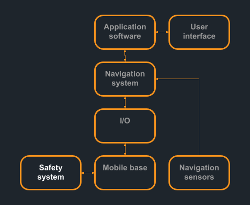
A navigation system for mobile robots will always attempt to avoid collisions. Still, this is generally not enough to ensure safety. Especially in industrial applications, a redundant safety system is required in most cases. This can be assembled in several ways. Which type of configuration suits your robot best depends on the application and the associated risks.
Sensors
At low speeds and for lightweight robots, a safe bumper that engages the brakes or disables the motors can be sufficient. In industrial applications however, this is seldom the case. This means possible collisions should be detected by another system.
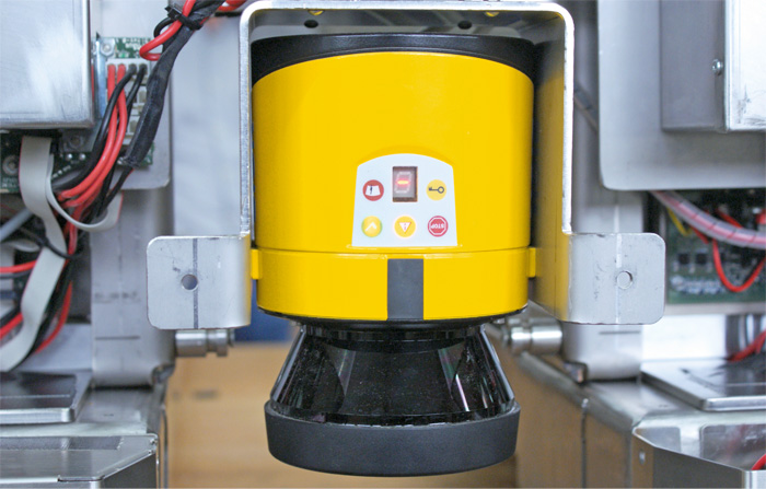
A frequently used sensor for this purpose is a safety lidar. The lidar determines the distance to objects in its environment using infrared laser beams, and switches one or more safe signals depending on its detections. The superior models can be configured with multiple zones for different threat levels or situations. One may choose to approach the loading dock of the AGV at a low speed, allowing you to use a less conservative safety field than during nominal navigation. It is important to take into account the positioning of the sensor in the vehicle design. For example, the height of placement must comply with safety regulations.
Another benefit of using lidar is that this can also be used as input to the navigation system. More often than not, this system uses lidar data to recognize its surroundings and determine the position and orientation of the robot. It can also use the lidar data for obstacle avoidance even before obstacles reach the safety fields.
Switching the motors off
The sensor or sensors provide input to some switching apparatus that ensures that the vehicle stops. Many industrial motors have a so-called safe torque off functionality. This allows a safe signal to stop the motor from providing any torque. Motors that lack this functionality can be switched off using a safety relay: a switch that removes power from the motors based on a safe signal.
For heavier vehicles, even this may not be enough as the vehicle will roll on due to its inertia. In this case, safe emergency brakes may be an option. An alternative is to safely short circuit the motors. This induces a torque opposite to the direction of rotation.
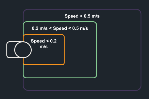
A safety-PLC allows one to program logic schemes for switching the safe output signal based on its input. The different zones of a safety lidar may trigger different behaviors depending on the current speed and the navigation mode. This makes the system less conservative and therefore decreases the downtime.
System integration
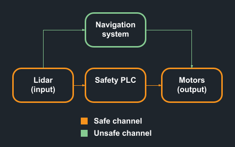
As mentioned above, the safety system functions to ensure safety where the navigation system cannot. This implies that it is imperative to have the two subsystems function independently of one another. Employing a “safe loop” is therefore strongly recommended. This loop of sensor, plc and motors is responsible for the safety. As a consequence, no “unsafe” elements are allowed to be part of this loop, because this would degrade the safety of the entire system. The navigation system can build on top of this safe layer, assuming the ensured safety by the safety system.
Getting to work
Are you planning to employ a safety system in your AGV or AMR? Make sure you get expert advice beforehand. Choices for bumpers at low speeds, or lidar with more advanced options, a safety PLC and the way you embed these into the AGV system are important and very much dependent on the risks involved in the application of your robot.
We’d love to hear what your application is about, and what kind of safety system you decide to use! Leave us a message via info@ruvu.nl or through the contact form on our website.